I was asked by the Singapore American School’s robotics program to develop a robotics kit for their intro course that was able to drive two small DC motors wirelessly at low cost. I picked the DFRobotics arduino-based gamepad as the controller and an arduino for the robot. The two arduinos (gamepad and robot) communicate using xbees, which are small wireless modules that are easy to interface with using serial port communication.
The source code for both gamepad and robot can be found here:
https://github.com/larsonmpdx/SAS-robot
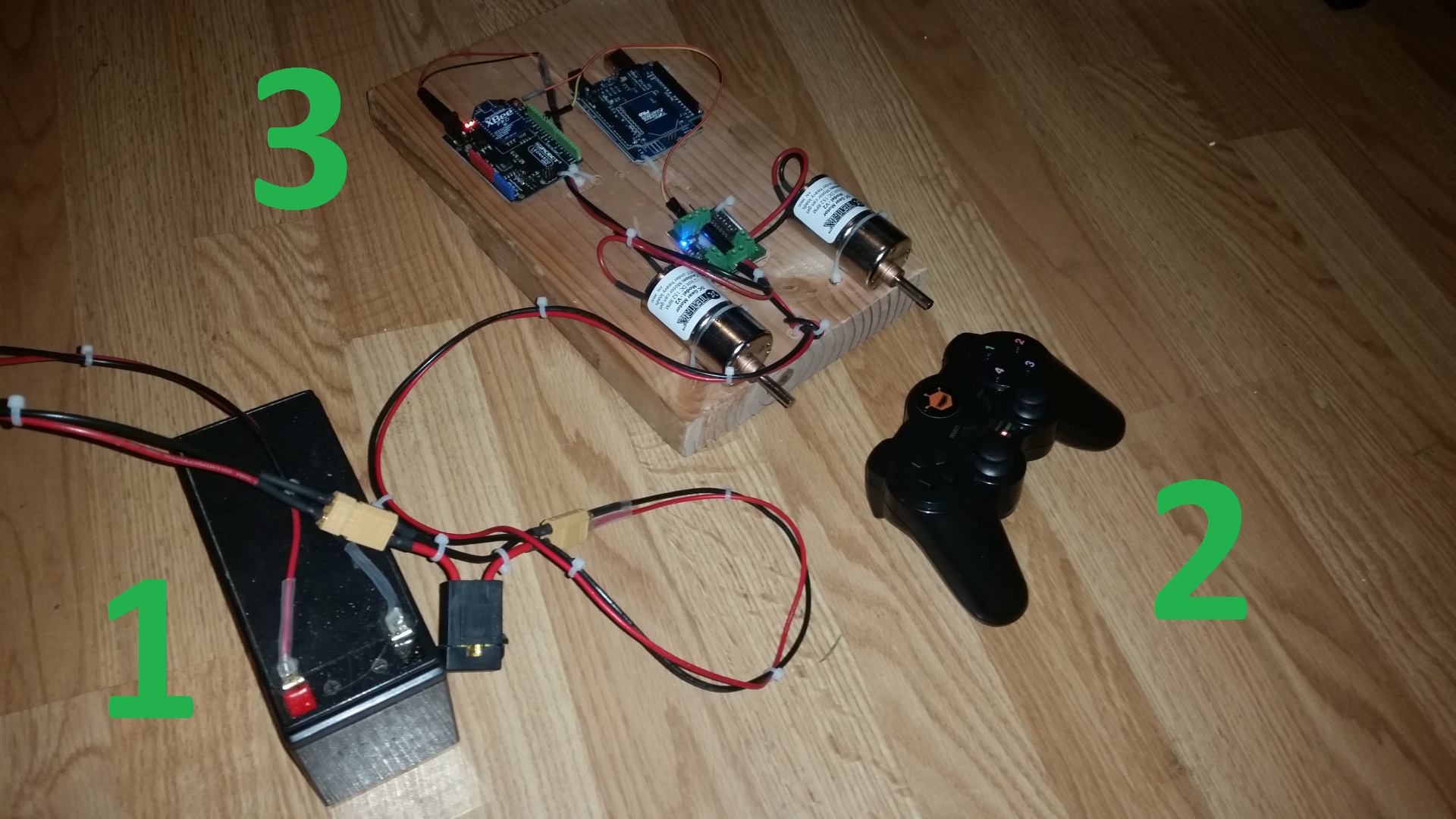
The readme at the github repository has most of the documentation. Here are some pictures:
- 12V sealed lead acid battery. inline automotive fuse holder + fuse. Yellow XT60 connectors (I put these on everything. As of 2015, they have decisively won the RC connector wars)
- DFRobot controller. Inside is an xbee series 1 60mW with wire antenna. This is an arduino with xbee socket built into a playstation 1 frame. It runs on 3 AAA batteries. Programming/debugging is done through a little usb connector board that plugs into an exposed pin header on the back. Don’t plug this in backwards! I fried the USB functionality doing this (you can still use ICSP to program it, but it’s a pain)
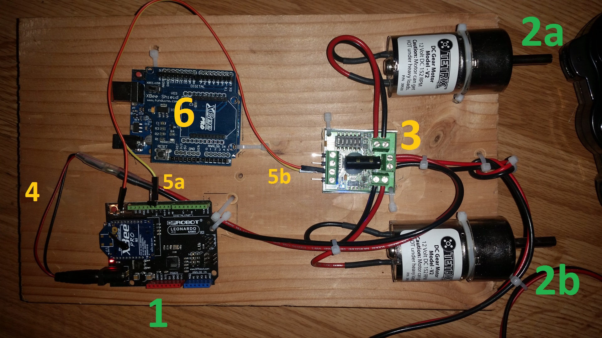
- Robot demo board
- DFRobot arduino leonardo with integrated xbee socket. This could also be a regular arduino leonardo with an xbee shield. Matching series 1 60mW wire antenna xbee
- a. b. tetrix DC gear motors. These are 12V and draw maybe 1-5A depending on load
- Dimension Engineering sabertooth 2×5 DC motor controller. This is hooked into 12V power, the two motors, and on the left side it has its control pins (I stuck pins in the terminal block to use a plug-on jumper). The jumper is plugged into S1 because it’s configured in serial control mode. The other pins in this block are GND, S2, and +5V BEC. GND isn’t connected because the arduino shares a ground already through a shared power supply. S2 isn’t used in this mode. The +5V BEC doesn’t supply enough current to power an arduino plus a 60mW xbee, so it isn’t used
- arduino power cord. These are available as pre-wired pigtails. I soldered this to an extension and connected it to the 12V battery. The connection is made at the motor controller’s input block by putting both pairs of wires in (near the number 3). The arduino’s power supply is a linear regulator and the arduino runs on 5V, so powering it with 12V makes the regulator drop a lot of voltage internally, heating it up. This works, but it’s at the limit of the arduino’s specs. Just something to be aware of.
- a. b. Signal wire from the arduino to the motor controller. This is a software serial port on the arduino on pin D11, connected to S1 on the sabertooth 2×5. The yellow wire is used, the orange wire doesn’t go anywhere.
- extra arduino UNO and xbee shield. I left this on the board to show another option. I started prototyping with this and realized that it can’t support USB debugging and the xbee communications at the same time (both use the same serial port, it only has one). I switched to using the arduino leonardo to gain an extra serial port for debugging. I do not recommend using an arduino UNO, for this reason.
See the github readme for more in-depth documentation. Overall, the kit works really well, with great control response time, good range with the 60mW xbees (I’m not sure how far – it covers my whole house), and OK gamepad battery life of a few hours (the gamepad needs 4 volts or higher to work well though, so I don’t recommend rechargeables). It’s fully programmable and my hope is that students will be able to extend its functionality easily, using my example code as a starting point.

